Home > Studio Recording DIY Projects> KRK RP8 Electronics
KRK RP8 Autopsy
As I said earlier, this RP8 monitor isn't working right. When you turn on the switch, you just hear this static sound.
At first I thought... maybe the amplifier chips are busted. I've worked with a similar type of one-chip amps back in the late 80s, and they're very fragile (at least, back then....). If they get shorted, it's gone... poof, bye bye.
Listening to the static noise, I noticed that the "noise and static" sound coming from woofer is the same noise and static coming from the tweeter.
This is important information. Why? If the amplifier chips are busted, then both the woofer and tweeter will be producing a different kind of static noise from each other. It will not be a clone of one another. And besides, if the amplifier chips are busted, then I shouldn't be hearing anything! I should only get a silent, quiet monitor.
Of course, this is just a guess. I need to verify if my guess is correct.
If both the LF amp, and HF amp are reproducing the same type of noise, then that means they're receiving the same type of input signal and they're just amplifying it. Noise In = Noise Out.
Where else can the input signal come from? From the Active Filter board! Where else?
To test my theory, I need to verify if the amplifier board is working properly.
So I disconnected the white ribbon cable that connects the amplifier board from the Active Filter board. I turned on the RP8, and what do you know! The static noise is gone! So far, so good.
Then I setup my signal generator and connected it to the LF and HF inputs of the amplifier board.
I flip the power switch for the RP8, and turned on my signal generator..... NO SOUND!
Hmmm...... this is not good. Why would the speaker make noise if connected to the Active Filter board, but not work when it's disconnected.
Then I remember the STAND-BY pin on the ribbon cable. I opened the PDF files for the amplifier chips and studied how the Stand By pins work for these chips.
I need to apply voltage to this STAND-BY pin to tell the amplifier chips "Hey, everything is alright. Go ahead and start up!"
For the TDA2052 chip (tweeter amp), Pin 3 must have a voltage > 2.7 Volts for sound to come out. Otherwise, there is a 100dB attenuation.
For the TDA7294 chip (woofer amp), Pin 9 must have a voltage > 2.5 Volts for sound to come out. Otherwise, there is a 90dB attenuation.
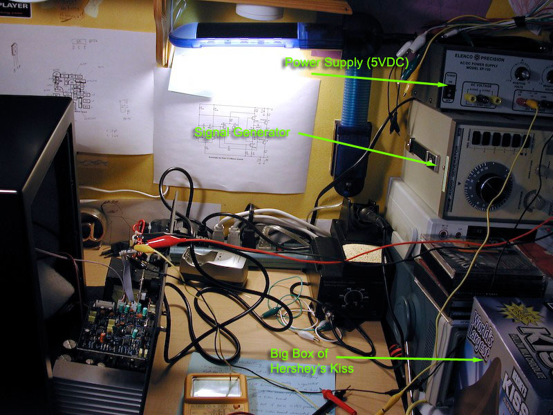
I don't want to measure 2.7 volts, (I'm lazy)... and I remember my bench power supply has a 5V DC fixed output. I thought, hmmm.... let me just use that. The specs didn't say it must be exactly 2.7 Volts, it just says it must be higher than 2.7 Volts! So I rigged this up.
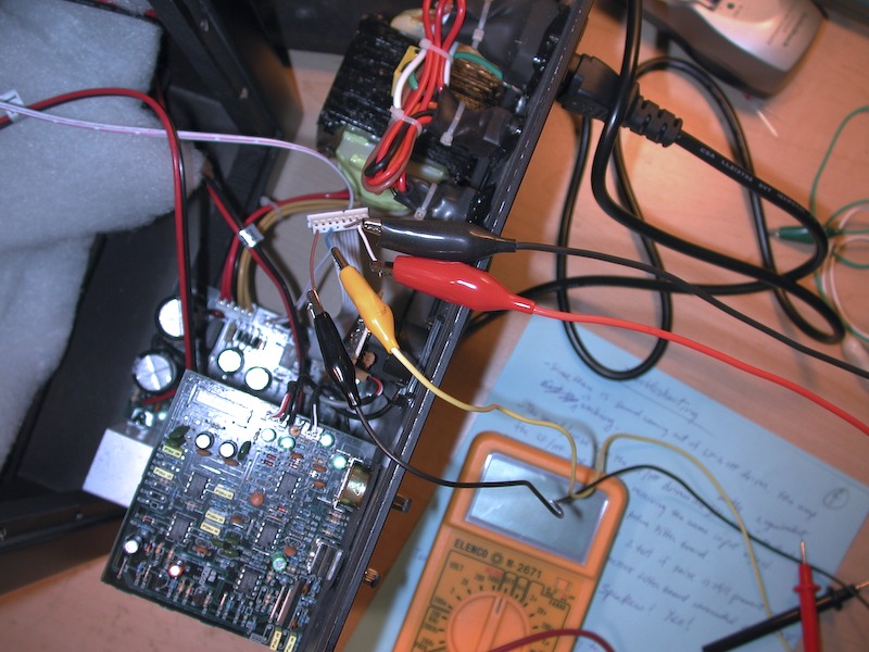
The 2 black alligator clip wires are for the ground. The Red alligator clip is coming from the signal generator, and the Yellow alligator clip is the 5VDC connected to the STAND-BY pin, coming from my bench PSU.
I powered on the RP8, powered on my signal generator, and powered on my bench PSU.
And what do you know.... the amplifier boards came alive and sound came out of the speaker. I tested both the LF amp and HF amp and they both work great! Nice clean sound!!!
The Good News and the Bad News
So the good news is the amplifier, psu and woofer, tweeter are working properly.
The bad news is the Active Filter board is defective. Which means, it's going to take more work to troubleshoot this because there are a lot more components involved.
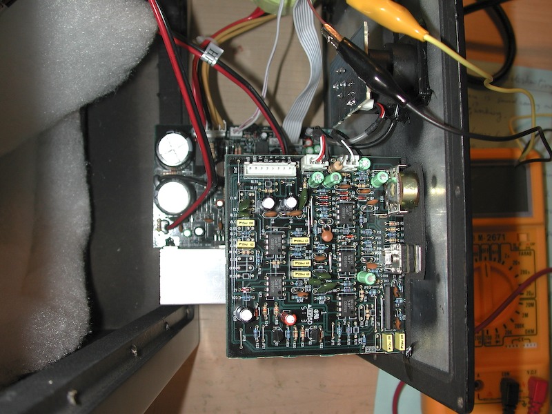
This is a picture of the Active Filter board that I will need to troubleshoot....
.