Home > Studio Recording DIY Projects> KRK RP8 Electronics
KRK RP8 Autopsy
The small chip to the left is a TDA2052 amplifier chip. Here is a link to the TDA2052 datasheet. It is a 7-lead chip, in a Heptawatt V package, Class AB (yes, AB! It is NOT a CLASS A amp). This chip requires a split PSU of 18-0-18 (maximum 36Volts).
It gives 40W rated output @ 4 ohms, typical. You can achieve 50W Max, using 36Volts. Total Harmonic Distortiaon (THD) at 4 ohm load is 0.1% typical, and 0.7% maximum.
This is the amplifier chip that powers the tweeter. I say modern technology is great. It's got great specs, and decent output power for such a small package!
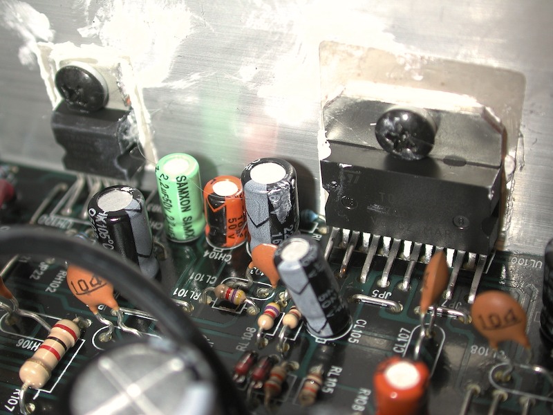
To the right, is a bigger chip. It is the TDA7294 amplifier chip. And here is the TDA7294 datasheet.
It comes in a Multiwatt 15V package, and requires +/- 40VDC for it's power supply. It is a DMOS type chip, also a Class AB amplifier (NOT Class A). One nice feature of this amplifier chip is a built-in turn on delay.
It can give 100W RMS typical at 10% THD, 50W at 0.01% THD typ, 0.1% max.
I think that 100W RMS at 10% THD is pretty high... but that's just my opinion. I'm just reading the specs of the chip, okay? Here it is again if you want to read it. TDA7294 datasheet.
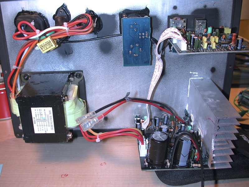
Here is another shot (at a different angle) of how the whole thing is layout.
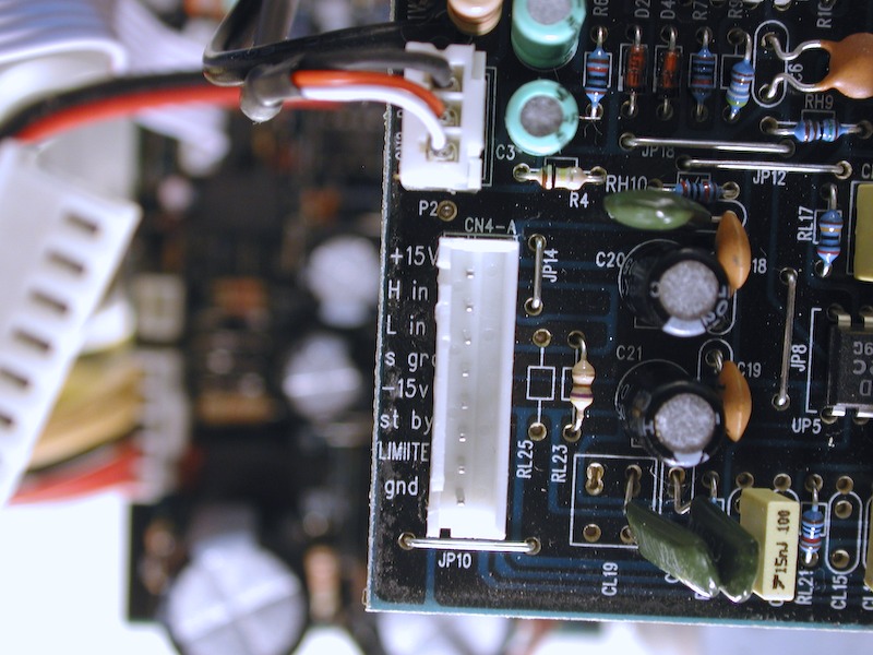
As I stated earlier, one of the pins in the ribbon cable is a Stand By pin.
The TDA2052 (tweeter amp) has pin-3 as the stand-by pin. The TDA7294 (woofer amp) has pin 9 as the stand by pin. These pins control when these amp chips turn on or off. Basically, the RP8 uses these pins to avoid the "popping" sound you get when you turn on the unit. I think it's a much better solution than using power-on delay relays.
.