Home > Studio Recording DIY Projects> DIY Midi Controller
Next step:
I'm thinking of adding an LTC module so I can have some LED lights for the midi input and output signal... i.e. to show midi activity. The LTC module will also allow me to add a second MIDI OUT port.
I need to get a PIC programmer, preferably one that is USB connected and cost less than $50. This will allow me to experiment with PIC chips and PIC programming.
I need to find a suitable case for this project. I'm thinking of getting a case similar to an Access Virus, but since this is just a test-build, I don't want to spend anything big on the chassis. So maybe I'll build this project using cardboard or plywood and when everything is working great, then that's when I'll start constructing the final chassis.
Front Panel Design
I want to make the layout of the pots and buttons ergonomically efficient. So instead of finalizing locations on an expensive aluminum sheet, I used cardboard!
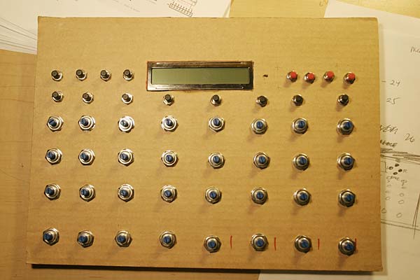
The top 4 buttons are the function keys, F1, F2, F3 and F4. The four red buttons on the right are the navigation keys, SAVE, LEFT, RIGHT, EXEC.
There are eight channels and each channel has a pushbutton. There are 4 pots per channel... (from top to bottom, they are SEND1, SEND2, PAN, LEVEL).
The LCD screen is located on top, centered. It will be backlit.
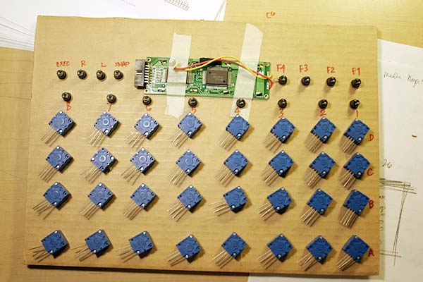
And this is what it looks like behind the cardboard box.
Now, the next step is wiring 32 potentiometers, 16 buttons, the LCD panel, the CORE module, Analog Input module, Digital Input Module, MIDI jacks, and power supply. Whew! Just typing that is a lot of work. This is going to be a lot of work.
Cut... strip... solder.... The Joys of Wiring
Okay, we start wiring this puppy. Here are some photos. You need a gameplan when you're wiring 32 pots, 16 buttons and all the interconnects between the different module. Plan ahead, visualize, and try to stick to your plans... there is no shortcut!
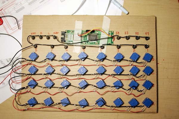
On this photo, you can see the ground wire (black) that is common to all the switches, and the ground and positive wire (red) for the pots. The pots basically can send anywhere between 0 volts to 5 Volts to the Analog Input module, depending on where the pot is turned. These 0 to 5V then get translated by the Operating system to MIDI values 0-127.
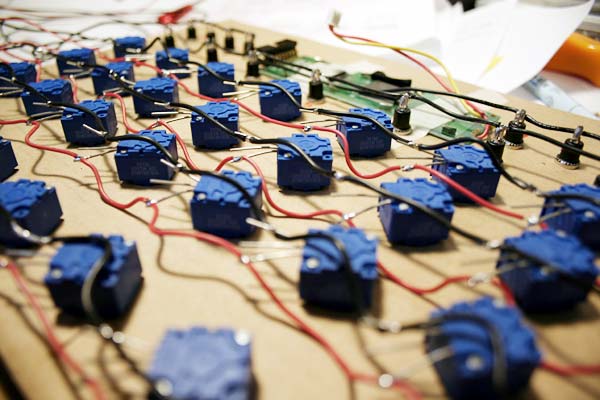
Closeup of the wiring... yes, 32 pots multiply by 3 terminals per pot = 96 solder points for the pots alone.

Closeup of my soldering job. You can also see the sealed-type Bournes potentiometer.