Home > Studio Recording DIY Projects> Altec 1599A Upgrade
Outputs of the mic preamps enter thru the left Molex connectors. You'll also see six (6) resistors, one for each channel that tie all the outputs together. (I told you, the design is simple!) From here, it goes to a line preamp driver, composed of (3) transistor in TO-92 packages (left side of blue capacitor). The amplified output goes to the silver capacitor (middle, below the 7818 black thingy) and down to the Molex Connector. This wire then connects to the RCA output jack. The output is the "mixed" version of the 6 channel mic preamps.
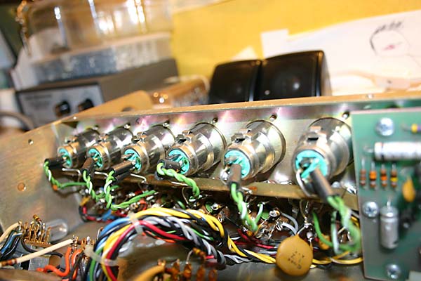
Here's a picture of the XLR connectors. The XLR wires go to the preamp can's inputs.
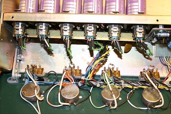
The output of the preamp cans then go to pad, and potentiometer. The potentiometer acts as a volume level control.
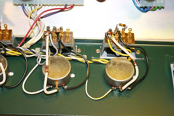
Again, a very simple design/wiring. From the volume level potentiometer, it goes to the PCB where the "summing" and additional "amplification" takes place. (see upper left corner).